Decimal to BCD to ASCII. Ask Question. The task is to take in a decimal number, convert it to BCD and then to ASCII so that it can be displayed on a microcontroller.

Now we will write another Assembly program to convert ASCII code to its BCD equivalent. Let’s identify variables needed for this program. First variable will be the one which will hold the values entered at Console in its ASCII code and it will be NUM. Other variable will be holding BCD equivalent of the ASCII code and it will be BCD. Other variable will be holding the Message “ENTER CHARACTER” to be printed for the User, So in all Three variables. The identified variables are NUM, BCD and MESSAGE.
First Line – DATA SEGMENT DATA SEGMENT is the starting point of the Data Segment in a Program and DATA is the name given to this segment and SEGMENT is the keyword for defining Segments, Where we can declare our variables. Next Line – MESSAGE DB “ENTER CHARACTER:$” X DB?
MESSAGE DB “ENTER CHARACTER:$” this line is a declaration of Charater Array initialized with “ENTER CHARACTER:$” and $ is used as ( n) NULL character in C program. (A Character is of a BYTE Hence we have to use only DB Define Byte ) NUM, BCD to? Stands for blank value). Detailed explanation is given below. Next Line – DATA ENDS DATA ENDS is the End point of the Data Segment in a Program. We can write just ENDS But to differentiate the end of which segment it is of which we have to write the same name given to the Data Segment.
Give More Feedback
Now, Selection of data type is DB data type because Character needs BYTE which means DB is sufficient. DATA SEGMENT MESSAGE DB 'ENTER CHARACTER:$' NUM DB? ENDS In Assembly programming, the variable are all defined by bytes only. DB – Define Byte (Size – 1 Byte) DW – Define Word (Size – 2 Byte) DD – Define Double word (Size - 4 Bytes) DQ – Define Quad word (Size – 8 Bytes) DT – Define Ten Bytes (Size – 10 Bytes) NUMBER SYSTEM in Assembly Programming is Decimal, Octal, Hexadecimal, Binary. In the Program, We are entering the values for the variables and Do arithmetical Operations like Addition, Subtraction, Multiplication and Division So the Computer should understand which kind of Number is entered. Hence there is a different letters for different Number Systems.
O or o stands for Octal, H or h stands for Hexadecimal, B or b stands for Binary, D or dstands for Decimal. By default type of numbering system is Decimal. If you do not specify any letter then the number is understood to be Decimal (By default). DATA SEGMENT MESSAGE DB 'ENTER CHARACTER:$' NUM DB? ENDS CODE SEGMENT ASSUME DS: DATA CS: CODE START: MOV AX, DATA MOV DS, AX LEA DX,MESSAGE MOV AH,9 INT 21H MOV AH,1 INT 21H MOV NUM, AL SUB AL,30H MOV BCD, AL MOV AH,4CH INT 21H ENDS END START Explanation: In this Assembly Language Programming, A single program is divided into four Segments which are 1. Data Segment, 2. Code Segment, 3.
Stack Segment, and 4. Extra Segment. Now, from these one is compulsory i.e. Code Segment. If at all you don’t need variable(s) for your program.


Main hoon na online. If you need variable(s) for your program you will need two Segments i.e. Code Segment and Data Segment.
Next Line – CODE SEGMENT CODE SEGMENT is the starting point of the Code Segment in a Program and CODE is the name given to this segment and SEGMENT is the keyword for defining Segments, Where we can write the coding of the program. Next Line – ASSUME DS:DATA CS:CODE In this Assembly Language Programming, their are Different Registers present for Different Purpose So we have to assume DATA is the name given to Data Segment register and CODE is the name given to Code Segment register (SS,ES are used in the same way as CS,DS ) Next Line – START: START is the label used to show the starting point of the code which is written in the Code Segment.: is used to define a label as in C programming. Next Line – MOV AX,DATA MOV DS,AX After Assuming DATA and CODE Segment, Still it is compulsory to initialize Data Segment to DS register. MOV is a keyword to move the second element into the first element. But we cannot move DATA Directly to DS due to MOV commands restriction, Hence we move DATA to AX and then from AX to DS. AX is the first and most important register in the ALU unit.
This part is also called INITIALIZATION OF DATA SEGMENT and It is important so that the Data elements or variables in the DATA Segment are made accessable. Other Segments are not needed to be initialized, Only assuming is enhalf. Next Line – LEA DX,MESSAGE MOV AH,9 INT 21H The above three line code is used to print String or Message present in the character Array till $ symbol which tells the compiler to stop. Now, lets understand line by line LEA DX,MESSAGE in this LEA stands for LOAD EFFECTIVE ADDRESS and it loads the effective address of second element into the first element.
This same code can be interchangably written as MOV DX, OFFSET MESSAGE where OFFSET means effective address and MOV means move second element into the first element. MOV AH,9 INT 21H The above two line code is used to PRINT the String or Message of the address present in DX register. Standard Input and Standard Output related Interupts are found in INT 21H which is also called as DOS interrupt. It works with the value of AH register, If the Value is 9 or 9h, That means PRINT the String or Message of the address present in DX register. Next Line – MOV AH,1 INT 21H MOV NUM,AL The above three line code is used to Read a Character from Console and save the value entered in variable NUM in its ASCII form.
Standard Input and Standard Output related Interupts are found in INT 21H which is also called as DOS interrupt. It works with the value of AH register, If the Value is 1 or 1h, That means READ a Character from Console, Echo it on screen and save the value entered in AL register. MOV NUM,AL means move value in AL register into variable NUM. Now, lets understand line by line Next Line – SUB AL,30H MOV BCD,AL The above Two line code is used to convert the value entered in variable NUM from ASCII form to its BCD form. This can be done by subtracting 30H i.e.
See More On Stackoverflow
The value coming from Console is Basically in ASCII form. When you enter 5 we see 35H,So by subtracting 30H we get back to value as 5. SUB AL,30H means subtracting 30H from AL.
MOV BCD,AL means move value in AL register into variable BCD. Next Line – MOV AH,4CH INT 21H The above two line code is used to exit to dos or exit to operating system. Standard Input and Standard Output related Interupts are found in INT 21H which is also called as DOS interrupt. It works with the value of AH register, If the Value is 4ch, That means Return to Operating System or DOS which is the End of the program.
MOV AH,4CH This same code can be interchangably written as MOV AX,4C00H where AX register is initialized with 4C00H which means 4C gets saved in AH register and 00 gets saved in AL register. Different books follow different forms. Next Line – CODE ENDS CODE ENDS is the End point of the Code Segment in a Program. We can write just ENDS But to differentiate the end of which segment it is of which we have to write the same name given to the Code Segment. Last Line – END START END START is the end of the label used to show the ending point of the code which is written in the Code Segment. Note:- In this Assembly Language Programming, We have Com format and EXE format.
We are Learning in EXE format only which simple then COM format to understand and Write. We can write the program in lower or upper case, But i prepare Upper Case. Screen Shots:- Output:- Variables ( Before Execution):- Variables (A fter Execution):- Note:- To see the variable and its value you have to click vars button in the emulator. Note:- To understand program for sequence in detail Please SEARCH numerically example: ASSEMBLY01, ASSEMBLY02, etc. Category: Tags:,.
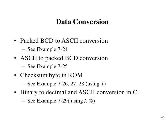
SECTION 6.5: BCD, ASCII, AND OTHER APPLICATION PROGRAMS In this section we provide some real-world examples on how to use arithmetic and logic instructions. We will see their applications in real-world devices covered in future chapters. For example, many newer microcontrollers have a real time clock (RTC), where the time and date are kept even when the power is off. These microcontrollers provide the time and date in BCD. However, to display them they must be converted to ASCII. Next, we show the application of logic and rotate instructions in the conversion of BCD and ASCII. To ensure the integrity of the ROM contents, every system must perform the checksum calculation.
The process of checksum will detect any corruption of the contents of ROM. One of the causes of ROM corruption is current surge, either when the system is turned on or during operation. To ensure data integrity in ROM, the checksum process uses what is called a checksum byte. The checksum byte is an extra byte that is tagged to the end of a series of bytes of data.
To calculate the checksum byte of a series of bytes of data, the following steps can be taken. The checksum generation and testing program is given in modular form.
We have divided the program into several modules (subroutines or subprograms) Dividing a program into several modules (called functions in C programming) allows us to use its modules in other applications. It is common practice to divide a program into several modules, test each module, and put them into a library. The checksum program shown next has three modules: It (a) gets the data from code ROM, (b) calculates the checksum byte, and (c) tests the checksum byte for any data error. Each of these modules can be used in other applications. Many ADC (analog-to-digital converter) chips provide output data in binary (hex).
To display the data on an LCD or PC screen, we need to convert it to ASCII. The following code shows the binary-to-ASCII conversion program. Notice that the subroutine gets a byte of 8-bit binary (hex) data from PI and converts it to decimal digits, and the second subroutine converts the decimal digits to ASCII digits and saves them. We are saving the low digit in the lower address location and the high digit in the higher address location. This is referred to as the Little-Endian convention, that is, low-byte to low-location and high-byte to high-location. All Intel products use the Little-Endian convention.